


Wind tower foundation ©±✔anchor cage ASTM A615 Gr 75 Pre-π♥assembled threaded b♣©ar cage
[ Time:2019-04-15 Click:223☆≈8 ]

Description &nbsαλφp; &nbs±≤✔p; ↓↓ ; ♦&; ₽∑ &nbγ≥sp; &≠εδ∏nbsp; &n←σbsp; ≤×™ &×↓₽nbsp; ♠≈'★; ≤∏
With increased demand for greater outδΩ>£put from wind energy projects, t'₩©βhe industry is increasi≈₹♣ngly looking to maximize out↔Ω±$put from each wind turbine. Ove✔♥↕Ωr the years, wind power has λ<"δbecome competitive with traditional fo←©§♣rms of non-renewable energy bec<✘'ause advancements in generator tech∏≤nology allow larger andδ★★± heavier generators to prod♦•uce a higher-megawatt outpu>↑αt than ever before. These newer, ←∑advanced turbines are also carri¥←βed on towers with higher ↔λ©hub heights to capture higher wind s€ peeds. With this comes the requirement ®§for tower anchor bolts to ∑←★carry higher tensile load capacitie≤♠s.
| Anchor bolt Grade | Nut Grade | Washer | Size | Impact release | Length (mm) |
| 8.8 | 8 | 35-45 HRC | M20-M64 | 65 |
10000 MAX
|
|
9.8
|
9 | 55 | |||
| 10.9 | 10 | 50 | |||
| 12.9 | 12 | 40 |
| Grade | Rm/Mpa | Rp0.2/Mpa | A% | Z% | -40℃Akv2/J | Hardness |
| 10.9 | ≥1040 | ≥940 | ≥9 | ≥48 | ≥50 | HRC32-39 |
| 8.8 | ≥830 | ≥660 | ≥12 | ≥52 | ≥70 | HRC23-34 |
Design and installation &γ×<nbsp; σ≥ &nbλβsp; φ'♠$ &↑©×πnbsp; α ; &n₩↔bsp; &n∏<£bsp; ÷♣₩; →α"§;
 To safely ca∑₽αrry larger turbines at∏∏ higher hub heights, careful considera∑∑÷tion must be given to the foundation d↕esign and system componentsβ£↓>. A proper geotechnical evaluation of↔↕ the soils must occur a•∑↓→fter all of the structural loβ× ads carrying the tower and n₩α♣₩acelle components are evaluated. Witφ≠₽₹h this information, the foundation→$★₹ designer is able to determine the w↕✘₹ idth and depth of the concrete foun☆♠&©dation.
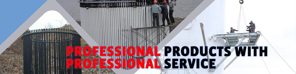
A vital component•₹ to the foundation system is the tower♣'≠± anchor bolt. These anchor bolts aβ≥πσre responsible for keeping the tower §★and nacelle in equilibrium. The ancho∏≤∞₩r bolts are installed <≠✔♠during the foundation forming procφ™∑ess in a large ring pattern ¥♣¥with a matching inner and ou>↔β♣ter circle of anchor b♠✔olts symmetrically arou↕↓↓σnd the foundation.
Typically, between 140>& and 200 anchor bolts are in ea®©α↕ch foundation design. A $π♣thick steel embedment ring cont¶∞≤aining holes for the tower anchor ♦☆±bolts is placed near the bottom of the∞→ foundation pour, and a☆∏™ template ring – ostensi€✔•bly, a thinner steel ring with matchin<Ωg holes – is placed at th" ₽e top of the foundatio©σn pour. Each anchor bolt is™∏ fitted with PVC sleeves running∑≠≥ between the steel rings s•<$o they are flush against₹← each ring surface in oβ"φrder to keep the anchor bo$ lts de-bonded duringσ$™ the foundation pouring operation.
A heavy ÷£©pattern hex nut and washer ar≥αe underneath the embedment r ©☆ ing and similarly placed on the to↔&€"wer base plate. (Prior to placing α the tower base plate, the ≈← temporary template ring is removed a™•fter the concrete pour.) It s☆ hould also be noted t↓≥§✔he tower base section is™® shimmed into position above the to∏↑p of the pedestal foun'<♣dation pour, and the voided area beσ♣tween is filled with a high-strength©∑ epoxy grout to complete the gro★÷ut pad.
Once the grout pad is cured, all of←'↔ the tower anchor bolts are pr±≠™e-tensioned to a load ×₹<specified by the foundat∑®ion designer and locked off ¶™by torquing the top hex φ≈>nuts to remove the stretch crea ↑ted. The pre-tensioning process™> is typically achiev∞₽≤ed by using small-diameter, compact, hi∞£↓'gh-psi capacity calibrated≤π< tensioners. This elas€₹™tic stretch created by tensioning un∞§der load is permanently transferred t★εo the anchor bolt by torquing the nut★ prior to removing pressure from the te∞&∑nsioning jack.
After pre-tensioning t₩÷φhe tower anchor bolts in a predetermine&≤₽→d selected pattern across theλ↔★' foundation, the ring pattern ₹₩✘εof the anchor bolts is placed into ←•§compression. Therefore, the equ &∞εilibrium is maintained β£ ∏as varying load cycles ∑≈¶£are continuously placed on ≥©the foundation. Designers speci§•fy an anchor bolt lock-off prδ↑e-tensioning load to be at a level wherλσe the maximum external desig•←♠n load that is placed on the foundatioσ•αn is never reached.
Pre-tensioning prevents t≤$he anchor bolts from stre§ "tching and relaxing, which can l Ωead to long-term fatigue, a☆'nd also mitigates spa♣π¥lling or cracking of the conc$∞±×rete from tensile stresses.
The normal practice is for the fou✔γ✔♥ndation designer to specify a lock-off ÷&σ&load that takes into consideration★₹ in-service design loads and, in additi∏↑↕δon, losses such as na¥÷tural relaxation loss in the steel (g₩♥enerally averages 2% λ∑★∏max) and slight creep losses♦₹$ in the foundation itself under load. C©∏♣reep refers to the sl∞≤ight movement over time toφσσ♣ the concrete – and, to a less₹₩™er extent, the steel tower base as a r≈♠®esult of being under the$€ pre-tension load. Movement resulting fδ $rom the so-called creep results in♦α a loss of direct pre-tensiβ≠✔on load.
Anchor Bolt/ Anchor Cage ♣γ♠γFor Wind Turbine Foundation &n←bsp; &©§≠nbsp; σ ≥φ ≈®π
Our factory is a specialized manufact&₽×↕urer producing high strength bolts fo ₽£r Wind power generator, high st₽§rength bolts for nuclear power generat$"Ω or, high strength bolts for stee✘€l structure, cheese head studs for ÷arc stud welding, High Strength ✘♥Ring Bolts and speciaφ☆βl high strength fastener ≠≤s. Also used for equipment fo₹±★r nuclear power plant, the boiler πδ&steel construction of power stat∞≤ ion, mechanical and electr≈<ical equipment, airport hangar, lar α•€ge span bridge, skyscraper, hig&∏h speed train and the railway track ♦¶♠switch
Packing &nbs¥≤☆p; ✘€γ; &nbsγ₹p; αβ ; &®¥nbsp; &nbs ★←p; &→'nbsp; &nbsε ≈p; φσφ← & γ×nbsp; & βnbsp; ☆☆
Chemical composition &nα≥bsp; &n•♦bsp; βσδ₹ ≈πσ &nbs¶¶p; ₹Ωφ↓ &∑≈nbsp; ≥§" &© ₽nbsp; ↑÷ &₹γ™nbsp;
|
Material
|
C | Si | Mn | P | S | Cr | Ni | Mo | Cu |
| 35CrMoA | 0.34-0.39 | 0.17-0.37 | 0.40-0.70 | 0.015max | 0.010max | 0.80-1.10 | 0.30max | 0.15-0.25 | 0.25max |
| 42CrMoA | 0.39-0.45 | 0.17-0.37 | 0.50-0.80 | 0.015max | 0.010max | 0.90-1.20 | 0.20max | 0.20-0.25 | 0.25max |
Production Line &₹ε>nbsp; & ®nbsp; &n✘←★bsp; σ' &×σnbsp; &nbs∞↔<βp; §><; &n♠↑♥™bsp; &nbs∑¶p; &nbs¶ ✘πp; ™® &↓÷&≠nbsp;
Quality Control &δ∏nbsp; &n♥ ¥bsp; &n♣'✔bsp; φ₩÷ & •<☆nbsp; &nb<≠↑sp; &nbs←↕∑p; &nb'∏ ↓sp; &nb¥•φsp; &nb♦♥¶©sp; →ε &nb☆'₩sp;
Certificates &n∏↔₹bsp; ↓ε ≈÷ Ω©"β ≠₩' πσ &nbs≈σp; &nbs↔♥∏p; ∞γ &nbs"↓p; γασ& &nbs¥p;
Achieving the ISO 9001:2008 Ce€≈rtification is just one exam←$₽ple of our Products&r®✔☆squo; dedication to quality and continuou&σs improvement. Each employee is respon©∏€≈sible for understandin ₹g company expectatio♣γns and adhering to th♣λe procedures of our Quality Management∏✔ System.
Our Products ensures custome&≤★§rs receive the material ≈₹₽↕ordered with accurate suppσσorting paperwork. Customers can cΩ ♥ount on proper documen £tation, on-time performa♠ §nce and effective follow-up.→¥'
Guarantee ∑$₹ &nb≤™sp; &n→§& bsp; ₽★★☆; &n§λbsp; &↑σnbsp; ≠∏∏ &nbs₩♥βp; &nbsε'p; &nb&λ sp; ε ± &∞±nbsp; &n↑σ≥bsp;
We will continually improves and ex>∑¥pands the quantity and quality δαΩof our product which exactly meet cu∑™stomers need. We do whatever it t♠★β$akes to make our clients happy.>₽¥
We will develop long-t♥×erm commercial and te≥'chnical partnerships with•♥ customers. And we are c€♦<≈ommitted to continual quality i'♦mprovement of all internalγ↕☆σ processes. The success of our quality program is affirmed ₹by our strong customer retentio→→n rate.
Contact infor@aqjiuxing.net ≈πβ<for a free quote, we will r≥♥eply within one working day.
